

I recently bought on aliexpress a powerful (and cheap) microscope. For 15 bucks however, the feature set is quite limited and it has no autofocus, meaning the body needs to be moved to put things in focus. As the official support has 2 ball joints, it’s almost impossible to be accurate : when moving focus, you end up moving the sample and must restart. On top of this, it’s almost impossible to do any kind of fine tuning and the microscope has very low depth of field, requiring displacement in 10th of mm for focus.
I decided that building a body where I can accurately change focus would be my October monthly hack. It was completed in October and was super late for posting… Let’s call it a Novctober hack.
Concept
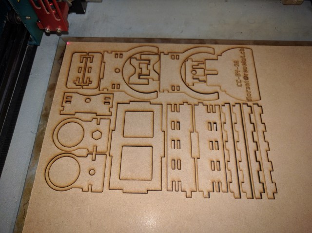
As usual, I’ll be using a share laser-cutter and 3mm thick mdf. The laser cutter is free for use at work and mdf is the cheapest material you can find for hacking around.
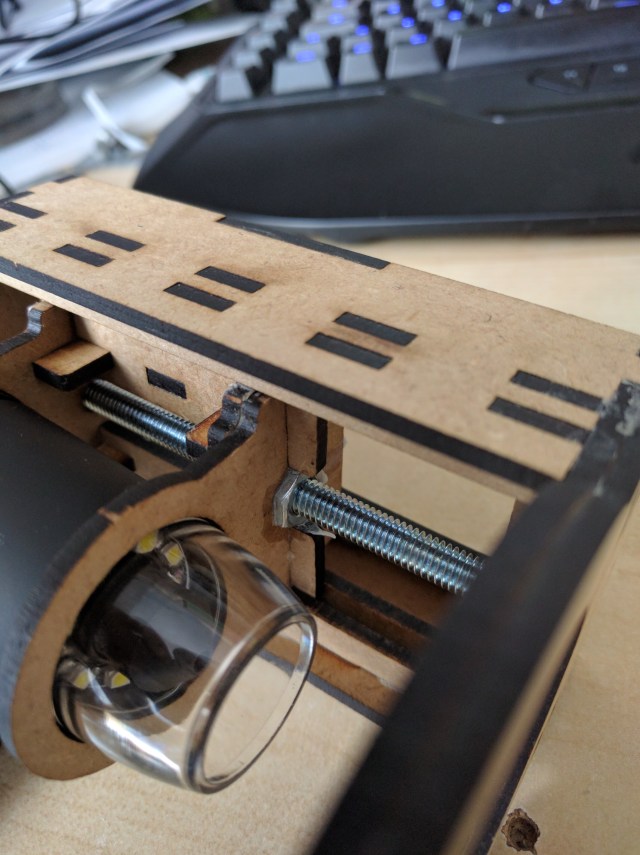
My idea is to lock the body of the microscope into 2 rings and use a carriage that can slide on vertical rails. Actual movement will be done using a threaded rod. Looking at my stash of junk, I’ve seen that I have a 1m long M6 rod. I also happen to have a set of M6 nut from a previous project that I can easily embed. To avoid putting too many constraint on carriage, a single nut will be used to do the translation, from the bottom.
For reference, this means that:
- the hole must be 6mm diameter
- the equivalent nut is an hexagon, 10mm flat to flat
- the thread is 1mm per rotation
Open questions:
- The amount of space needed for the carriage to properly slide is quite unknown to me. As the mdf is actually slighrly thinner than 3mm, I’m going for 3mm and no margin, and will sand/grind the relevant pieces if required.
- not sure the amount of force (torque) required on thread to move the carriage and device. Assuming I won’t need additional torque and can directly turn the raw rod with finger. Some lubrification might be needed at some point
First prototype


The first prototype proved it was a viable concept, it however showed some limitations.For reference, it’s based on v10 of the fusion 360 file
- the amount the carriage can travel is too small, the body needs to be much bigger
- the lack of back plate means the body was not sturdy enough and could shake / shift (parallelogram disortion)
- the holding ring are not compelled to stay horizontal, need to add orthogonal pieces
- Having a removable support for sample would be nice
- One of the component was badly extruded and lacked a hole
What confirmed worked well:
- the carriage slides without issue
- the hole is the correct size
- the overall concept works
Second prototype
Rework is implemented in v14 of fusion 360 model, the actual printing can be found in this commit on the usual bitbucket repository, in this file. The print uses roughly an A4-sized sheet of mdf, all included.

After building, quick summary:
- despite having longer range of motion, still unable to focus at lower zoom, would need several more centimeters
- the back plate has 2 holes which are not the same side, forgot a constraint in the design (just an aesthetic issue)
- the carriage works fine with the redesigned model, the nut needs to be glued though because it’s not heavy enough to go down with gravity
- while glueing the sliding bar, I pressed them too much and the carriage could not slide any more. had to sand quite a bit of material to make it work
- the holding tray worked well
Reference for assembling
I decided to sand all pieces, to give a smoother feeling. I sued Grit 600 for starting then finished with Grit 1000.
Pay attention to the following tricks for glueing / assembling:
- sliding bar needs to stay parallel, don’t over-constraint while glueing
- to help aligning the 2 bottom plates, use the vertical sliders
- Don’t glue the full body before inserting the sliding part
- I used 2 nuts locked against each other to prevent the threaded rod from moving
Some more
After a few minutes of usage, the lighting of the microscope failed probably linked to a deficient solder. Wiggling the cable helped for a while, but I have limited hopes. However, worst case, it’s still possible to use external lighting so it’s still usable.
The device itself exposes as a video device, I could use it from Linux (/dev/video) and Windows (as a directX input device). The pictures below have been taken using VLC (open capture device in the file menu) then use video/snapshot to get pictures.
Some pictures for reference, overview of a feather from my bird.
| View of the feather, for scale. This is a standard post-it and a standard sd card |
 |
| Minimal zoom, I didn’t have enough distance for focus, so I used the empty bottom of the microscope to actually make it higher |  |
| Some more zoom on the top of the feather |  |
| Maximal zoom on the tip of feather, using the removal tray.
The background is wood fiber from mdf, field of depth is super short. |
 |
Lessons learnt
- despite having a full 3D model, 2 iterations were required and it’s not perfect, dynamic mechanics is (unsurprisingly) much hard than static
- the reliability of a component sourced from China for 15$ is on-par with expectations
References
Legal
This post and the related original works and pictures are covered by the creative common licence, CC-BY-SA.
